So firstly, why? Well suffice it to say I was curious about what an old ride on lawnmower would do if I converted it to electric and hyped it up to go 70km/h. However, I was also in the mood to not sell my soul to a company like BorgWarner who make the popular Sevcon Gen4 controller which people would usually use for a task like this, and being the engineer I am... I decided I was up for the task of building a motor controller. A big motor controller.
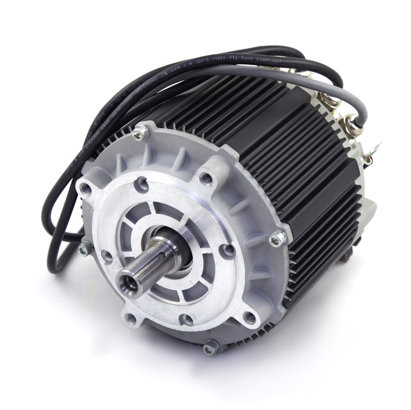
Firstly, the motor. I bought a Motenergy ME1718 PMAC (Permanent Magnet AC) three-phase brushless motor. These operate at voltages of up to around 72V, and at currents of up to 300A. That's over 20kW peak. These are therefore not your average drone, skateboard, scooter or e-bike motors: they're serious business, with serious power, weighing 13.5kg each.
So any 'sensible' engineer would have said, 'to make the best use of my investment, I should buy a high-quality, professionally-developed controller'. As I hope you've realised by now, I am not the 'sensible' engineer. And I don't regret it. Because if I'd just bought a Sevcon controller, this page would end here. Plus, Sevcon controllers are very restrictive. You need expensive software and dongles just to customise their settings, that software has a limited-length license that you'll need to renew, and it can only be installed on one computer system and can't be transferred. I don't support that sort of anti-consumer garbage.
The basic type of converter used to control this type of motor is a three-phase inverter. This has six semiconductor switches, which can connect each phase of the motor to a positive or negative supply, and operate using PWM (Pulse Width Modulation) to control the phase currents of the motor.
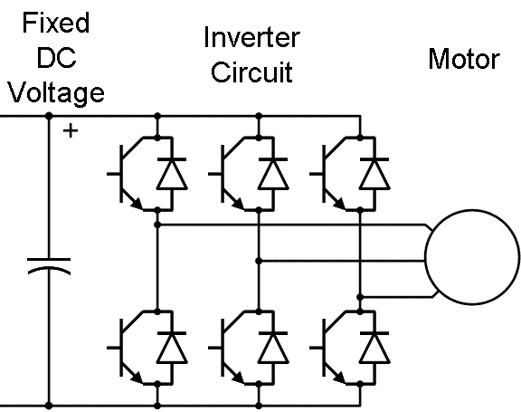
Combine this hardware with sensing of the current in each of the three phases, hardware to read the motor's internal encoder (position sensor), and an appropriate microcontroller to run Field Oriented Control (FOC), and you're done. Well, in theory.
In practice, that takes a quite bit of doing, given the high power level. How do you handle 300A? You can't just run a regular TO-220 MOSFET at those sorts of currents, or even a TO-247. I considered using perhaps two TO-247 devices in parallel for each switching leg of the converter, but eventually settled on using five TO-220 devices in parallel. Why? It comes down to losses. For example, say I can buy a 5mΩ TO-220 device that can handle 50A, or a 5mΩ TO-247 device that can handle 100A (because it's larger and can dissipate more power). However, two of the 5mΩ TO-220 devices might take approximately the same space and cost about as much, and handle approximately the same amount of current as the TO-247 device, but now the total resistance is 2.5mΩ, which means the losses are halved. That means higher efficiency, and less cooling to worry about. And when you're handling upwards of 20kW, a 1% efficiency improvement means 200W less required cooling capacity, which is a big deal.
With lots of MOSFETs in parallel, current sharing becomes a consideration, but if the on resistance of the MOSFET dominates the total resistance of each parallel leg of the circuit, and the MOSFETs are on a common heatsink so they stay at a similar temperature, and you don't assume they'll share it perfectly, then the positive temperature coefficient of resistance of the MOSFETs seems to take care of things quite well.
Several factors make this easier too: it's low voltage, so 150V Silicon MOSFETs work well, and you can use a relatively low switching frequency, so switching speed isn't too crucial. I eventually chose 20kHz, because it's just outside of the audible range.
My goal isn't to go through every bit of the theory or knowledge required to design this type of hardware. My goal is to illustrate a few key parts that I learnt so that people walk away with a few useful learnings and are perhaps inspired, without being bored to death by detail that they'd have to figure out on their own anyway. So I'm not going to go into detail on FOC: instead I'll link you to this TI application report which has a great overview of it.
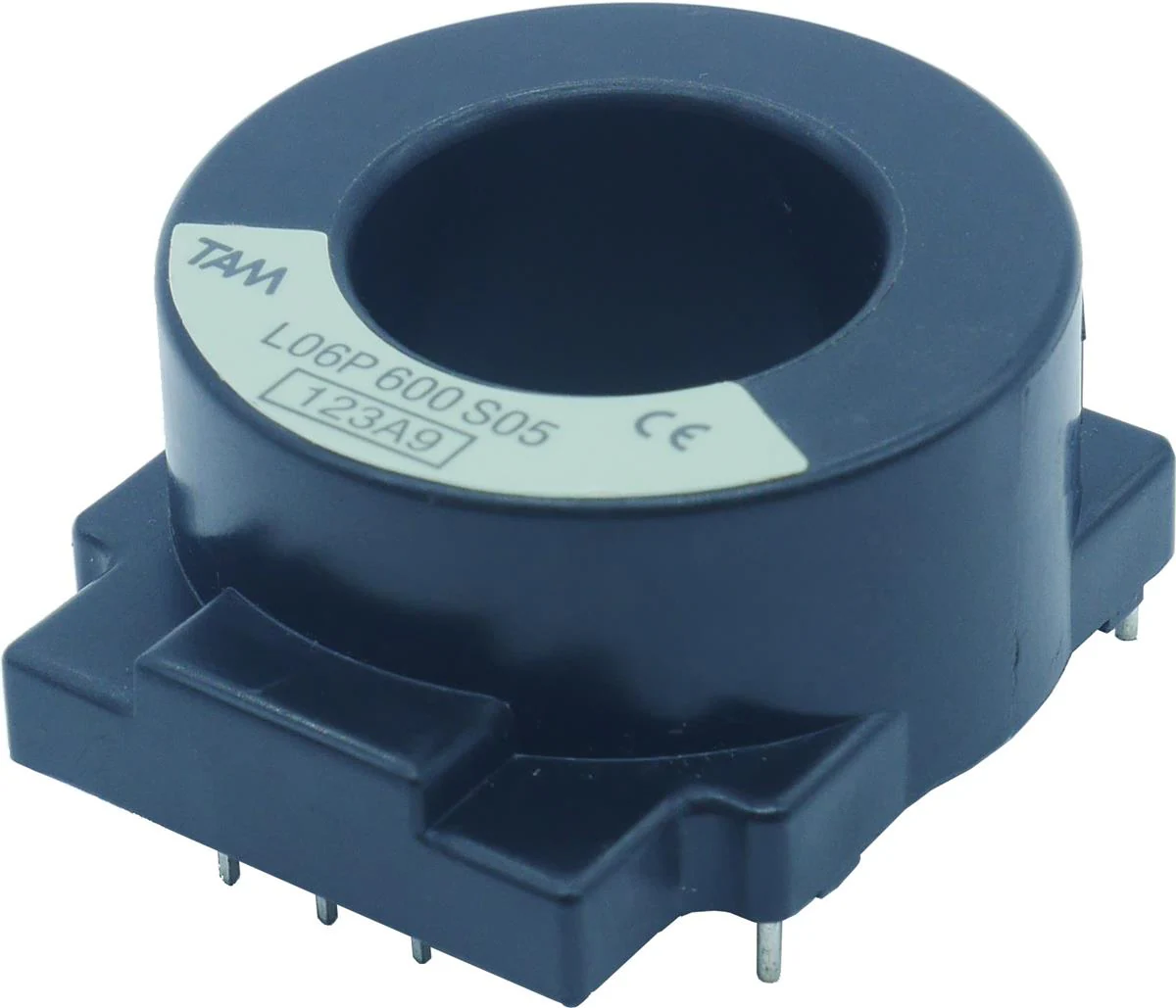
At 300A, using a shunt would be a difficult task, so I opted to use large hall effect sensors. The wire from the motor literally goes through the big hole in the sensor - and since these sensors are designed to be PCB mounted, the wire also goes through a cutout in the PCB itself. Hall effect works well for this because the fundamental frequency of the current through the sensor is simply the electrical frequency of rotation of the motor, which in the case of the ME1718, is simply five times the mechanical speed of the motor (it's got 5 pole pairs). Since this is still well under 1kHz, heating of the sensor core isn't a problem.
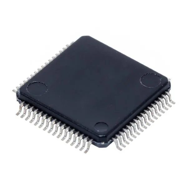
Having used the Texas Instruments C2000 series of microcontrollers previously, it was a natural choice for me. I'm sure you could use many others, but I knew the familiarity was going to make my life a lot easier, and it did. I selected the TMS320F280049C series, which is a single core 100MHz part, i.e. several times less powerful than what I've used previously. The benefit of this was that, as a 64-pin LQFP part, I was able to solder it easily, instead of buying a development board with a large BGA part pre-soldered. That also required some extra layout work for the power supply capacitors and onboard timing crystal, but none of that has been an issue. And it still turned out to be overkill: I haven't ended up using the CLA (Control Law Accelerator) at all yet, so I'm utilising less than 50% of its processing power.
Worth mentioning, when you have over $300 worth of MOSFETs in the converter, is protection. Developing a new control algorithm was rough on the hardware, with instability issues causing overcurrents frequently in the early days. Nonetheless, I only ever killed one single TO-220 MOSFET in the development of this controller, and that was due to a dead time issue which I subsequently corrected. The secret behind this almost unbelievable money-saving was having integrated circuits built into the gate drivers that measure the on-state voltages of the MOSFETs, to use them as a shunt resistor, and shut down if they (1) have too high of an on-state voltage or (2) switch on too slowly, both of which are indicators of a circuit problem. I set this up and tested it prior to developing the rest of the controller, so that the protections were there from the start. This was combined with software protection that disables the entire converter if any of the three phases exceeds a safe current, which proved very effective as well, eventually meaning I wouldn't trip the hardware protections at all, even during complete instability and wild current oscillation, because the currents change relatively slowly and it's easy for the microcontroller to shut things down if the control system has lost it, before they reach unsafe levels. I still think it's important to have hardware-based protections regardless of this, in case of software bugs, sensor issues, etc., and as a general failsafe. And also because the hardware protections are still a lot faster, if the current does get high enough to trip them - which could happen quickly if a short-circuit happens somehow (more on this later).
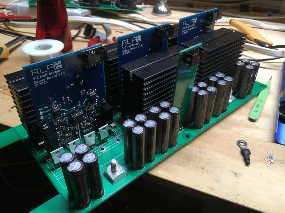
To make efficient use of 3D space, I opted to use a multi-board construction technique. I used one large power board at the bottom to house all the high-current components, namely MOSFETs, DC-link capacitors, and input/output connectors. Three vertical gate driver boards sit between the high and low side MOSFET banks for each leg of the inverter, with gate drive connections on the top side of the power board and large power planes on the bottom. At the top, the control board houses the microcontroller, signal processing and the three hall effect current sensors.
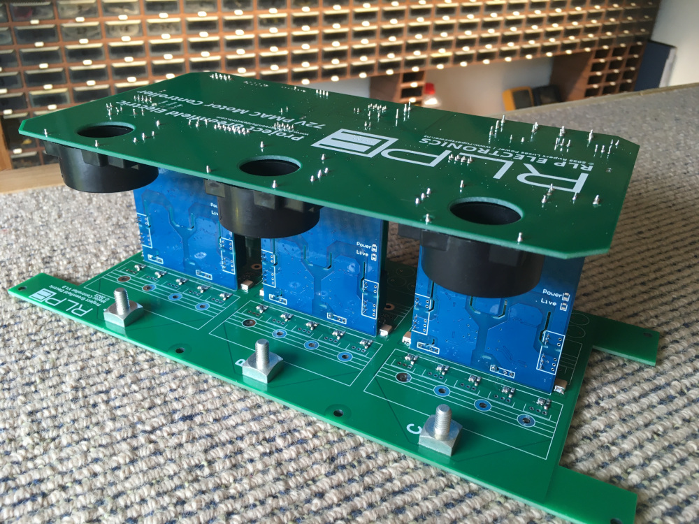
This is convenient as it means the sensors are close to where the signals are needed. It also meant I could make the bottom PCB 2mm thick for added rigidity and use 2 ounce (70 micron) copper there, without increasing the cost of the whole system, and I didn't need four-layer PCBs anywhere. The gate driver boards were in fact made using leftover PCBs from the same v1.0 design I produced for my inverter project, because they worked so well first time that I didn't see the need to make any modifications for this project.
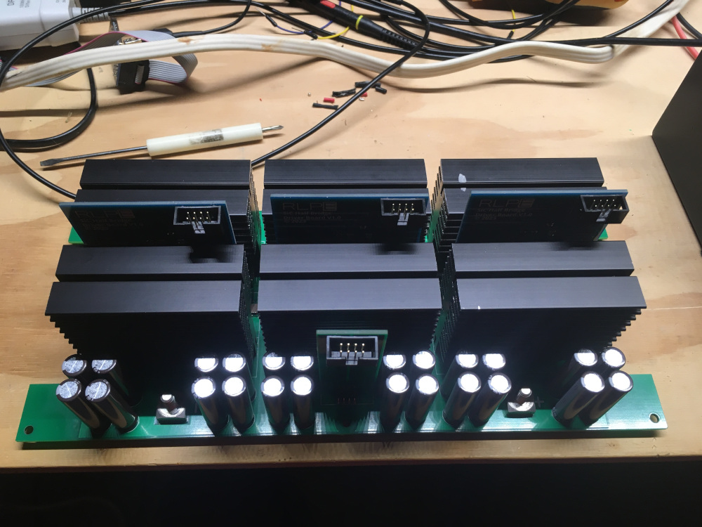
Each bank of 5 MOSFETs is attached to a large aluminium heatsink, and there is a cutout at each end of the board for mounting of two 80mm fans for a push-pull fan configuration. I included fan speed control circuitry on the control board because I just can't stand fans running at full blast when they don't need to, and smooth fan speed control is trivial compared to the rest of this system.
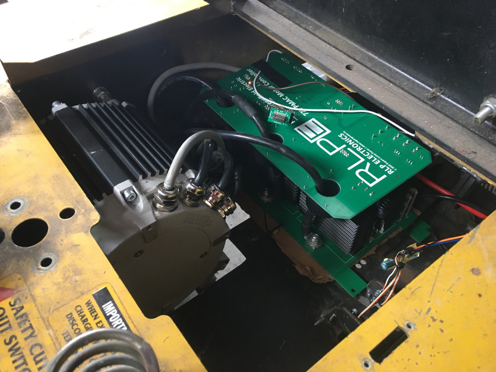
An enclosure is in the works, but I wasn't going to wait for that to deploy the controller for testing purposes in the... uhm... 'light electric vehicle'. So I just bodged it in. Cardboard may have been involved.
By and large the hardware worked fine, and I developed my FOC control code on it. No MATLAB, no Simulink, no LabVIEW, no BS - just straight C code, TI Code Composer Studio (based on Eclipse) and an oscilloscope. I ended up with about 1000 lines of code in the end, for the implementation of this project. There is more inside the TI library functions that I used, but I'm only using their DriverLib files for the microcontroller, not their actual motor control software, so it's fairly simple stuff. The 1000 lines even includes variable declarations, UART code, and fan control. I reckon this is a substantially more efficient implementation than most bloated commercial products.
Once I started load testing, i.e. driving the actual vehicle from the motor, and increased the current limit in steps, I eventually ran into an issue. At the point where I increased it to 250A, up from 150A, I killed that one MOSFET I mentioned earlier, dead short. Why didn't more MOSFETs die? Well because my gate driver protections are apparently fast enough to even protect from shoot through, so that dead high side MOSFET didn't result in further damage to the low side MOSFETs when they switched on and created shoot-through. The response time of the protection is 1 microsecond after all - this is the advantage of having hardware protections as a backup to software ones. And yeah, I repeated that test a lot of times for the heck of it - I couldn't fault it. Increasing the dead time of the gate drivers has prevented any further re-occurrences of the problem, and I have since increased the current limit all the way up to 350A without issue. Since the MOSFETs are rated for 150V, I see no issue with using the controller on DC voltages of up to 80V, hence the 28kW rating (350*80=28,000).
You bet it does. And there's nothing quite like the experience of getting to actually drive with a controller you designed and coded from scratch.
I've gotten up to around 50km/h on it, and I'm not sure I'll ever go faster, unless someone lends me a race track or unused airstrip and a racing suit. It's honestly terrifying at that speed with zero suspension, and no roll cage for safety either. Perhaps one day I'll write more about how this machine can actually cut grass, because it can - but for now, eat my dust BorgWarner.
None yet!
Display Name
Email (optional, not displayed)
Website (optional, displayed, include "https://")
Comment (up to 1000 characters)