I built an inverter, which doubles as a battery charger for my motor control/light electric vehicle/electric lawnmower project - and I thought it might be interesting to share how it went. Arguably this was a harder project than the 28kW motor controller I built subsequently, despite its lower power level, because it involved not just electronics and firmware design, but also multi-core firmware, magnetics design, and a focus on safety for high voltage/high power systems. Plus I've actually built the enclosure for this one at the time of writing, unlike the motor controller.
So firstly, why bother making it so high power, or why not make it bigger? Well the primary reason for the 4kW rating is to do with the power grid. Standard household outlets are rated at 10A, which is around 2300-2400W depending on your definition of line voltages (230V or 240V). I wanted more: my battery system is 8kWh and thus can easily handle charging at up to about 8kW, and short charge times are attractive. Going to a 15A household outlet gives you 3450-3600W, again depending on your definition of line voltage - this is the largest common type of outlet, beyond which you'd have to get a special 32A outlet or use three-phase power, which are both fairly rare things in New Zealand households. So I set out to build a system capable of fully utilising a 15A outlet for charging purposes, and leant on the conservative side with some design choices, hence 3.6kW -> 4kW. Since this device doubles as an inverter, this also means being able to run any device - in inverter mode - that could normally be run on a 15A outlet (and I'll mention high-inrush loads later) from batteries. Again the 8kWh system can discharge continuously at up to 8kW, so the inverter is still the limiting factor - but to me, the 4kW power rating makes it a useful system, without making it excessively expensive and complicated.
This power level means that on the low voltage side, currents go up to about 60A, while on the 400V DC side they stay below about 10A, increasing to a maximum of just over 17A RMS at the AC input/output.
I'm going to bullet point this stuff so I can't ramble. Here's the specifications I've ended up with, largely repeated from my earlier post which has more details (and rambling).
Now here's broadly how that was achieved in terms of my design choices and components.
I definitely could have spent more on MOSFETs, and probably improved the efficiency a bit, but it was expensive enough as it was, and being fairly new to designs at this power level, I wanted to prioritise implementing things correctly. Plus I was worried I'd just blow up expensive devices and lose a lot of money. That didn't happen much, thankfully.
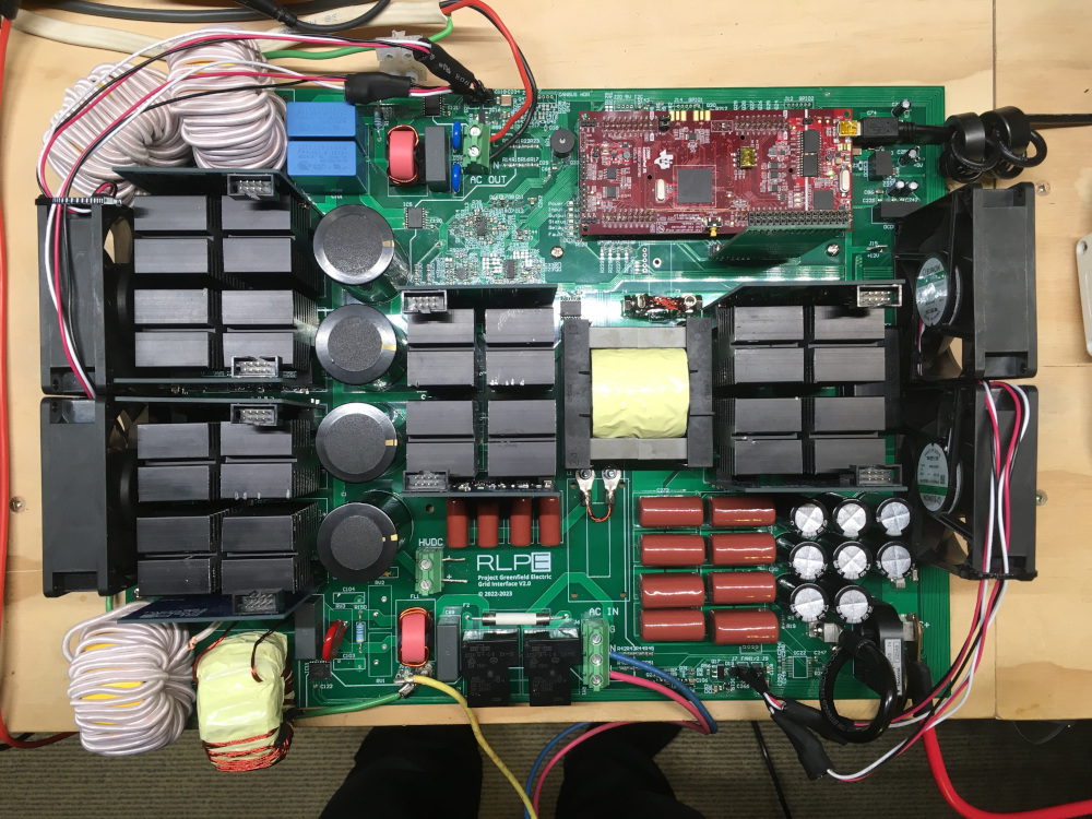
I elected for the all-or-nothing approach of putting all the major parts of the system on one board and hoping I hadn't stuffed anything up. It worked, somehow: largely because I planned for a few contingencies and thought very carefully about things before finalising the design. I prefer this approach as it is more convenient than having multiple boards dangling off wires and hence probably more EMI. I do however have vertical gate driver PCBs for each stage, and a second PCB on top interconnecting the control signals. Using vertical gate driver boards is a common approach, and it saved a lot of area on the main board while also allowing a pretty reasonable layout. Keeping the control signals up and away from the MOSFETs and magnetics seems to have worked well as I haven't run into too many interference issues.
As you'll notice in the photo below, there is a certain symmetry to the placement of the main power components, fans, and heatsinks. Was this necessary? No. Does it improve circuit performance? No. Does it really matter at all? Of course not. But am I bloody proud of it? Yes.
Rough efficiency data is shown below. I had a heck of time proving that my efficiency measurements were accurate. First I discovered that my clamp meter was reading slightly low, so I couldn't use that for any crucial measurements. Then I discovered that my AC power meter was broken and reading inaccurately. I measured the resistance of my DC input wiring and used it as a shunt, which was good until it heated it up and all the measurements went out the window because resistance goes up with temperature. I ended up fixing the AC power meter and verifying it against a Fluke 87V, and doing similar verification on the LV wiring 'shunt' at low currents and being mindful of temperature rise during testing. The final results appear reasonable albeit conservative when sanity-checked against the amount of heat generated by the converter, and other factors.
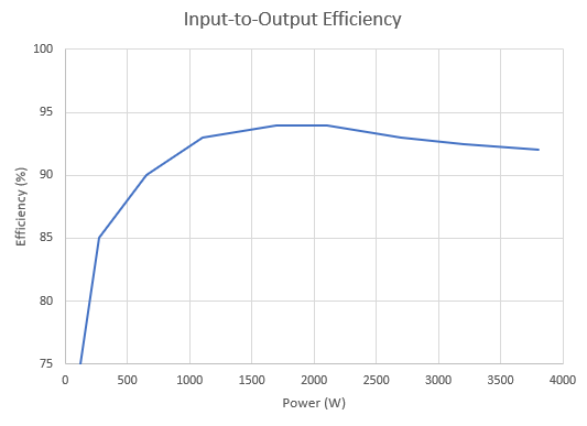
Keep in mind that this is the total efficiency of two converter stages back to back: a DC/DC converter, and DC/AC inverter stage. This means that at peak, the average efficiency of each individual stage is the square root of 0.94, i.e. 97%. Although I can't measure it at present because my high-power loads are AC, I suspect that the high voltage DC/AC stage is about 98% efficient and the DC/DC stage about 96% at peak. Given my design goals and initial expectations, this is really good. There are a lot of things that could be improved, from spending more money on MOSFETs to using different inductor cores to using more efficient gate driver power supplies. Most of them involve spending more money, increasing complexity or reducing functionality in some way, so are tradeoffs rather than mistakes as such, and no big design disasters glare out when I look back at it. I'd have liked the low-load efficiency to be higher, but the high-load efficiency is more important for charging, and mid-range is most important for inverter operation. The primary reason for the low-load efficieny drop is that the high-performance isolated gate drivers switching at high frequency consume a fair bit of power regardless of load. I also did not use a coupling inductor in the Dual Active Bridge DC/DC stage, instead relying on only the leakage inductance of the main switching transformer. This is an unusual choice which reduces costs and complexity and increases high load efficiency because it reduces conduction loss - but it reduces the load range over which Zero Voltage Switching (ZVS) occurs, meaning it hard-switches to a degree at low loads.
One thing I do think could be improved, even in-place on this particular prototype, is switching speeds: I had EMI issues early on and interference with the USB subsystem for the TI LaunchPad, and used higher gate resistors to reduce the switching speed on the high voltage side to reduce EMI. However, eventually I hardened the USB system by putting ferrite chokes on the cable, which proved much more effective - so the switching speed of most of the HV side MOSFETs is probably quite conservative. Some disassembly would be required to change the gate resistors again, hence I haven't done it yet - but I suspect it would produce some efficiency improvement.
I've lost count of the number of times I've seen current waveforms for grid-connected converters in research papers that just don't look quite... right. Maybe the power factor is still high, but they just ain't sinusoidal. I don't get it. Anyway, this is my grid current, thank you very much.
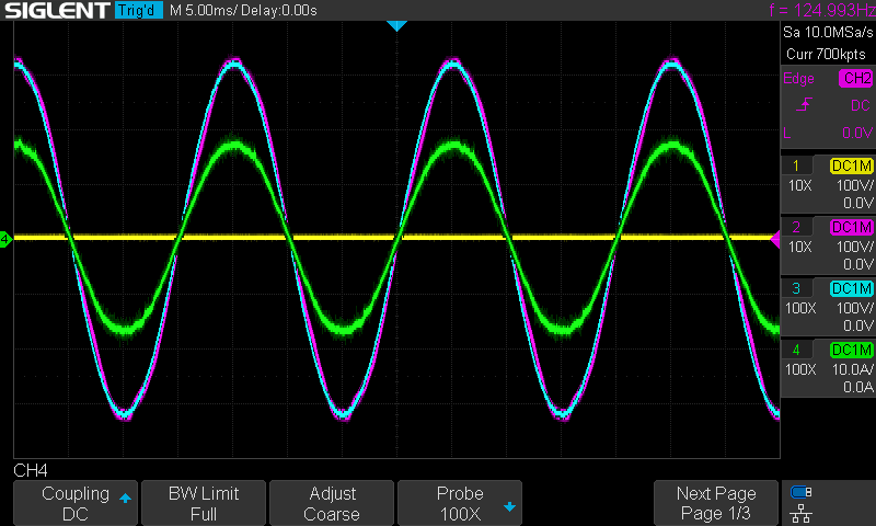
Digital Proportional-Resonant (PR) control does a fantastic job when tuned properly. I also used a PLL with a digital PI controller and a digital notch filter, which has worked really well. I've even tested charging from a noisy, unstable portable generator, and after some tuning managed this at up to 2kW (the point where the generator started bogging too much).
Well as it so happens, yes it can. Circular saws like the 1500W one I tested draw over 50A from the mains (well over 10kW) briefly due to inrush as the motor speeds up, making them an especially hard load to start. However, with the F28379D microcontroller at my disposal, I implemented a current limiting function that is much faster than the grid current and limits inrushes to a more reasonable 32A, and allows supplying overloads briefly. The voltage waveform gets a little bit messy during this type of operation, but less so than many commercially available inverters according to what users have documented online.
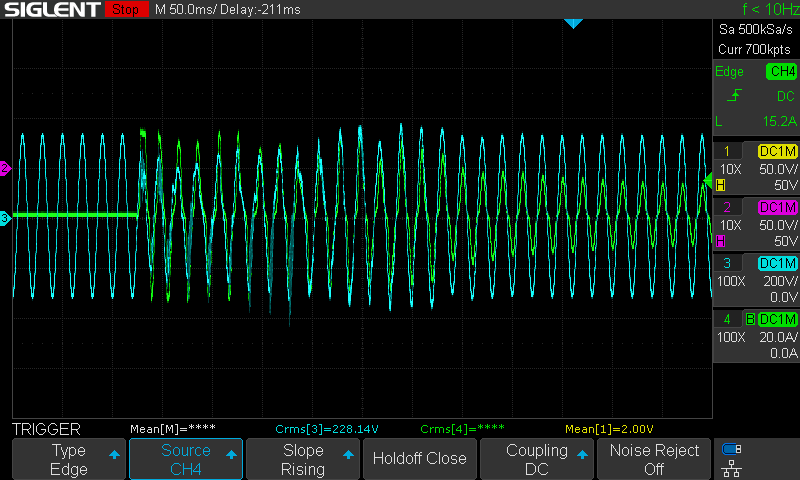
The power limits are almost all about thermal constraints since I used powdered iron output inductors that have a gradual saturation curve, so supplying overloads briefly for a startup inrush isn't a problem. I've also run angle grinders and even a welder off of this thing. It's pretty epic.
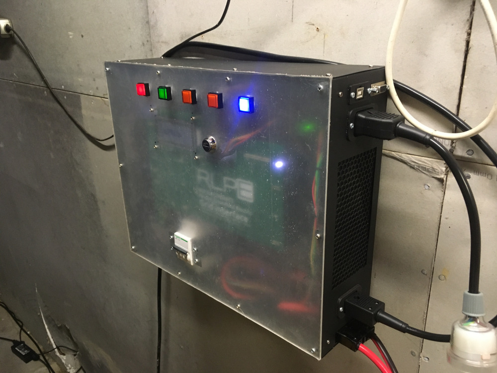
It wouldn't be complete without a box to put it in, and in my case wall-mount it. Many people would've bought some kind of enclosure. Some people might have 3D printed parts for one. I just got out my welder and made a frame out of 3mm steel bars! Then I made sides using galvanised steel plate, and cut holes where they were needed to mount things. I will say though... tapping over 30 M3 threaded holes through steel to attach the panels was not my idea of fun.
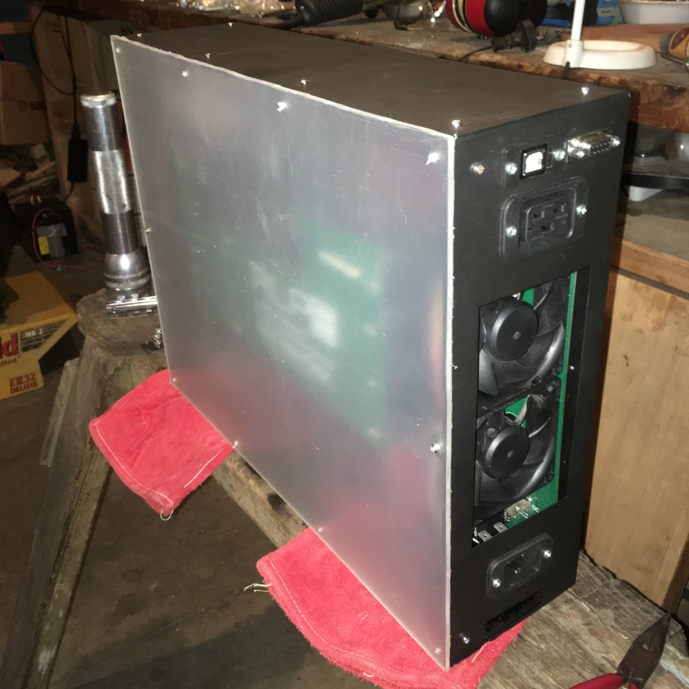
I made an acrylic glass front so you can see inside, which is currently only translucent as I haven't removed the protective film (it's still a work-in-progress). The buttons and indicators on the front are for user interface purposes and will eventually be labelled, and there will also be a LCD. Communication and control can also be done over RS232, and firmware programming over USB. As you can see, there is a nice Schneider Electric MCB on the front which is 16A Z-type and protects the mains input. There is also a 20A HRC fuse on the live conductor on the PCB, and a 100A HRC fuse on the LV DC side as well. My battery setup also has a fuse within the battery string, so that shorts directly at the output terminals don't cause some kind of nuclear explosion.
Well, thanks for reading I guess. Hopefully this has been something of an insight into the design and construction of a high-power system. I learn by doing, and learnt a lot by doing this. Within reason, I hope this is inspiring to others, and shows that this sort of thing can be done if you have the time and energy for it. I did not burn down any buildings or injure any living beings with this project, but as always, common sense safety precautions go a long way. If I can recommend just one thing, it would be to think carefully about your specific situation, rather than relying on general safety advice from the internet. Make sure you understand the nature of the equipment you are using and what can happen if things go wrong, and the nature of electric shocks at different voltage/current levels. Envison the worst-case scenarios that could occur - and there are a few of them in a project like this - and think about what your plan is for each.
As I've mentioned in various other posts, I take quite a strong approach to preventative circuit protection, i.e. protections integrated into the gate drivers to very quickly (think nanoseconds to a couple of microseconds) turn off the MOSFETs during short circuits such that they don't fail and go boom. This means I haven't encountered most of the contingencies I planned for, which is great. I'm still ready for them though.
Bearing in mind that this is not legal advice, my understanding is that the legality of building and using such a system at home is similar to buying something uncertified from an overseas supplier and using it - which many people do. There is nothing specifically illegal about it from the consumer's perspective - but insurance coverage for any damage resulting from the use of such a system is a grey area. In my case, doing this was important enough to me to take that risk, and seemed reasonable in context given that I understand the innards of this system completely and have built in several contingencies in case bad things happen. It seems both safer and more necessary to me than, say, buying a cheap e-scooter with an uncertified and potentially unsafe battery, and/or driving dangerously - and many people do those things. Your opinion and risk tolerance may vary, so as always, consider your specific situation.
None yet!
Display Name
Email (optional, not displayed)
Website (optional, displayed, include "https://")
Comment (up to 1000 characters)